Fet Is Used as Amplifier in Which Region
Cut-off region Saturation region O d. The cutofftriode regions are used if FET is operated as a O a.

Pin On مكاترونيك
In this region of FET it can be used as a.

. Among these three regions when MOSFETs are used as amplifiers they should operate in an ohmic region where the current flow throughout the device increases when the applied voltage is increased. When characteristics of a Field effect transistor for a fixed gate voltage are observed its seen to behave like an ohmic device and follow ohms law until a pinch off or saturation point is achieved. It is preferred during oscillation circuits.
The most common type of FET amplifier is the MOSFET amplifier which uses metaloxidesemiconductor FETs. Low-level signal amplifier is usually biased in the linear response region. These are used in the cascade amplifiers.
For VGS0 V the value of VDS at which ID becomes essentially constant is the pinch-off voltage VP. What is the pinch off value of JFET. In the below image a basic N-channel MOSFETs internal construction is shown.
Ed of O a. The CMOS complementary metal oxide semiconductor process technology is the basis for modern digital integrated circuits. The ohmic region is a region where the current IDS increases with an increase in the value of VDS.
This is pretty much wrong to say that the Field Effect Transistors aka FETs cant be used as voltage amplifiers infact they were made to be used as voltage amplifiers. MOSFETs exhibit three regions of operation viz Cut-off Linear or Ohmic and Saturation. Triode region O b.
Both cut-off and triode region can be used Answer. Answer 1 of 2. In the saturation region the MOSFETs have their I DS constant in spite of an increase in V DS and occurs once V DS exceeds the value of pinch-off voltage V P.
None of the options Clear my choice Next pag. When MOSFETs are made to operate in this region they are used as amplifiers. Among these when MOSFETs are to be used as amplifiers they are required to be operated in their ohmic region wherein the current through the device increases with an increase in the applied voltage.
FETs particularly MOSFETs are more costly to design as compared. For operation as a switch the cutoff and triode regions are utilized To operate the MOSFET in the triode region we must first induce a channel Create PDF files without this message by purchasing novaPDF printer. Amplifier Clear my choice Time left 02 Determine the region of an NMOS transistor when VG 2 V Vs 1 V Vé 1 Vps 1 V.
When MOSFETs are made to operate in this region they are used as amplifiers. MOSFET provides very high input impedance and it is very easy to bias. For the current limiting circuits JFETs are preferred.
The most common type of FET amplifier is the MOSFET amplifier which uses metaloxidesemiconductor FETs MOSFETs. For analog switching the FET is preferred. High-level amplification calls for saturation setting but one should expect some distortion.
The most commonly used FET is the MOSFET. For MOSFET is to be used as a switch then it must operate in A. When a MOSFET is operated as an on -switch it works in the triode or ohmic region When a MOSFET is operated as an off -switch it works in the cut-off region When a MOSFET is operated as a controlled current device it works in the saturation region Saturation refers to the channel being saturated.
A FET amplifier is an amplifier that uses one or more field-effect transistors FETs. Which FET is widely used. MOSFET Analogue Switching MOSFET Switching Operation n-channel E-MOSFET.
The ohmic region is a region where the current I DSincreases with an increase in the value of V DS. So for a linear small amplifier MOSFET is an excellent choice. Is BJT cheaper than FET.
The main feature behind this is that its input capacitance is low. But for a MOSFET to produce linear amplification it has to operate in its saturation region unlike the Bipolar Junction Transistor BJT. A FET amplifier is an amplifier that uses one or more field-effect transistors.
The main advantage of a FET used for amplification is that it has very high input impedance and low output impedance. Instead of sinusoidal output it is rather rectangular pulse series with. This is partly because BJTs were commercially available long before FETs were but the BJT has other advantages such as more predictable voltagecurrent characteristics and producing a large current change for a small input voltage.
In amplifier application the FET is always used in the region beyond the pinch-off. On the whole BJTs are much more used in amplifiers or at least historically they have been. Generally MOSFETs work in three regions like LinearOhmic or Cut-off Saturation.
It is the region where the drain-source channel resistance is at its maximum and there. Jan 8 2012. The saturation region is used if the FET is to operate as an amplifier.
In both regions it can perform the task of a switch. E-MOSFETs are generally used for switching applications. Mostly signal amplifier circuits are made by bipolar junction transistors like common-emitter transistors but where a small signal has to amplify where FET is used as an amplifier.
When VGS VGSth ÆMOSFET is off Ævery high RDS When VGS VGSth ÆMOSFET is on Ævery low RDS VGS must be sufficiently higher than VGSth to be in the upper end of load line in the Ohmic region 9-5. If we compare between BJT and MOSFET MOSFET or Metal-Oxide-Silicon FET is an excellent choice for small signal linear amplifiers because of its extremely high input impedance which makes them easy to bias. The linear amplification occurs when we bias the MOSFET in the saturation region which is a centrally fixed Q point.
If you rather use the MOSFET to switch onoff saturation setting can be useful for a good efficiency. In this way the field-effect transistors have many applications. Input impedance in this category of the transistor is better than BJT and offers less value of distortion for the output generated signal.
None of the options O b. Only in the saturation region a MOSFET can operate as an amplifier. The Ohmic Region of a FET transistor also called the linear region is the region where the drain current I_D has a linear response to changes in the drain-source voltage V_DS and the FET acts like a voltage controlled resistor 2Pinch-off region.
FET operates in four region 1Ohmic Region. MOSFET Amplifier Simple Circuit.

What Is Mosfet Its Applications Structure And Working Principle Science Stuffs Digital Circuit Principles Science
![]()
Field Effect Transistor Fet Jugfet And Igfet Explained

Anazor Connections And Applications Of A Jfet Amplifier Common Emitter Impedance Matching

Power Mosfet Construction Operation And I V Characteristic Basic Electrical Engineering Electronics Basics Electronic Engineering

Output Characteristic V I Curves Of Junction Fet Electronics Basics Transistors Electronics Technology

Igbt Insulated Gate Bipolar Transistor Electronic Circuit Projects Transistors Electronics Basics

N Type Mosfet Characteristics Curves Cnc Software Diy Electronics Amplifier

Power Mosfet Construction Operation And I V Characteristic Basic Electrical Engineering Engineering Subjects Power

Enhancement Mode Mosfet Curves Electronics Basics Semiconductor Materials Semiconductor

Jfet Amplifier Junction Gate Field Effect Transistor Is The Simplest Type Of Field Effect Transistor That Can Electronics Circuit Transistors Resistors

Introduction To Transistors Types Baising Modes And Advantages Transistors Diy Amplifier Electronic Parts

Introduction To Mosfet Depletion And Enhancement Mode Applications Enhancement Transistors Engineering
Pin On Ee Life

Field Effect Transistors Basic Fet Amplifiers Source Degeneration Improves Paperback Walmart Com In 2022 Transistors Circuit Design Amplifier

N Channel Enhancement Type Mosfet 2n7000 As A Switch Iamtechnical Com Basic Electronic Circuits Switch Channel

Introduction To Mosfet Depletion And Enhancement Mode Applications Electronic Engineering Enhancement Electronics Basics
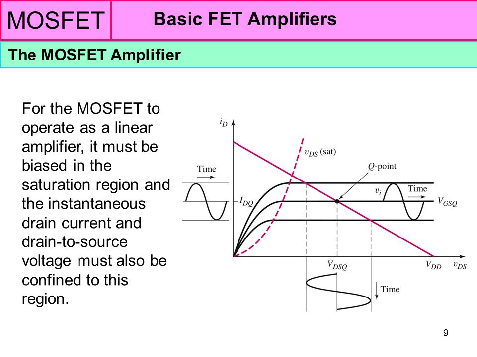
Mosfet Basic Fet Amplifiers The Mosfet Amplifier Ppt Video Online Download

Junction Field Effect Transistor Jfet N Channel Jfet Biasing V I Transistors Junction Electronic Engineering

7 Characteristics Of Jfet Transistor Transistors Electronic Engineering Junction


Comments
Post a Comment